Forces and free-body diagrams are key concepts in physics, helping us understand how objects interact. Forces are vector quantities that describe interactions between objects, including contact forces like friction and normal force.
Free-body diagrams visually represent forces acting on an object, making it easier to analyze physical situations. They show forces from the environment, like gravity and tension, using vectors originating from the object's center of mass.
Force Vectors
Forces are described by vectors.
- Vector quantities have both magnitude (size) and direction (ex. East, Up, Right)
- Force, Displacement, Velocity, and Acceleration are all vector quantities
- Vectors can be represented by arrows, with the length of the arrow representing the magnitude
- Example: A 5m arrow would be smaller in length than a 50m arrow to reflect the difference in magnitude
- A force can be simply described as a push or pull
- The sum of two or more force vectors is known as the resultant force (calculated using vector addition)
- Force vector acting on an object can be calculated using Newton's second law: F = ma


Forces as interactions
Forces as vector quantities
- Describe the interactions between objects or systems as forces, which are vector quantities 🏹
- Occurs due to the interaction of an object with another object or system
- Cannot exert a net force on itself, an object or system
- Force is always the result of an interaction of two or more objects
- No object has force on its own and no object can exert a force on itself
- Example: When you clap your hands, one hand exerts a force on the other

Contact forces
- Result from the interaction of an object or system touching another object or system, contact forces
- Arise as macroscopic effects of interatomic electric forces
- Examples include:
- Friction between two surfaces (always opposite to the direction of motion)
- Normal force exerted by a surface on an object resting on it (always perpendicular to the surface)
- Forces can be classified as either contact forces (require physical contact) or field forces (act at a distance)
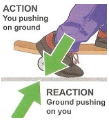
Force Pairs 🤝
- When one object exerts a force on a second object, the second object always exerts a force of equal magnitude on the first object in the opposite direction
- Newton's Third Law: "For every action, there is an equal and opposite reaction"
- In every interaction, there is a pair of forces acting on the two interacting objects
- The magnitude of forces is equal
- The direction of forces is opposite
- Forces always come in pairs - equal and opposite action-reaction force pairs
- Action-Reaction Pair: the force exerted on an object is the action, and the force experienced by the object is the reaction
- Example: A foot pushing down on Earth ↔ Earth pushing up on the foot
Force pairs always act in opposite directions, but they do not always cancel each other out
- The net force on a body is the sum of all forces acting on it
- Common force pairs include:
- Gravity: Two bodies attract each other due to their mass
- Normal force: Surface exerts upward force to balance gravity
- Tension: When a rope or string is pulled tight
- Friction: Resistance between surfaces
- Applied force: Direct pushing or pulling
- Spring force: Resistance to deformation
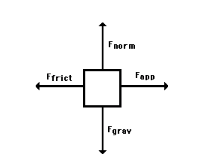
Free-body diagrams
Visualizing forces
- Serve as useful tools for visualizing forces being exerted on a single object or system
- Free-Body Diagram: A technique used to illustrate all the external forces acting on a body
- The body is represented by a single dot or box
- Only forces acting on the body from the outside are pictured
- Help determine the equations that represent a physical situation
- Provide a clear, visual representation of all forces acting on an object or system
Forces from environment
- Depict each of the forces exerted on the object by the environment, the free-body diagram of an object or system
- Include forces such as:
- Gravitational force (weight) 🌍 (always points downward)
- Normal force from surfaces (always perpendicular to the surface)
- Tension in ropes or strings
- Applied forces (pushes or pulls)
- Friction (always opposite to the direction of motion)
- Include forces such as:
Vector representation
- Represent forces exerted on an object or system as vectors originating from the center of mass representation (e.g., a dot)
- Treat the system as though all of its mass is located at the center of mass
- Draw force vectors as arrows pointing in the direction of the force
- The length of arrow should represent the magnitude of the force
Coordinate system selection
- Simplify the translation from free-body diagram to algebraic representation by selecting a coordinate system with one axis parallel to the direction of acceleration of the object or system
- Set one axis parallel to the surface of an incline when drawing a free-body diagram of an object on an inclined plane
- Choose a coordinate system that aligns with the primary direction of motion or acceleration 📐
Key Points about Force Vectors
- A force vector is a quantity that has both magnitude and direction
- The magnitude of a force vector is the strength of the force, while the direction is the line along which the force acts
- Force vectors are represented by arrows, with length representing magnitude and arrow direction representing force direction
- The resultant force is calculated using vector addition
- Newton's second law (F = ma) relates force vectors to acceleration
- Forces can be contact forces or field forces
- Common force vectors include gravity, tension, friction, and applied force
Example Problem
A box with a mass of 10 kilograms is being pushed across a floor by a person. The person is applying a force of 50 newtons to the right, and the floor is exerting a friction force of 30 newtons to the left.
- Draw a diagram showing the force vectors acting on the box.
- Calculate the resultant force acting on the box.
- Use Newton's second law of motion to calculate the acceleration of the box.
Answers
- Diagram showing a box with a rightward force of 50 N and a leftward force of 30 N
- F = F1 + F2 = 50 N + (-30 N) = 20 N to the right
- F = ma = 20 N = (10 kg)(a) where a = 2 m/s² to the right
🚫 Boundary Statements
On the exam, students are only expected to depict the forces exerted on objects, not the force components on free-body diagrams. Individual forces represented on a free-body diagram must be drawn as individual straight arrows, originating on the dot and pointing in the direction of the force. Individual forces that are in the same direction must be drawn side by side, not overlapping.
Frequently Asked Questions
What is a force and how do I know when two objects are interacting?
A force is a vector that describes an interaction between two objects or systems—it has magnitude and direction and always comes from another object (CED 2.2.A). Examples: weight (gravity), normal, tension, friction. Contact forces are when objects touch (macroscopic result of electric forces); field forces (like gravity) act at a distance. You know two objects are interacting if one exerts a force on the other (and by Newton’s third law the other exerts an equal and opposite force back). Practically: if an object’s motion changes (acceleration) or you can identify a contact or field source (floor for normal, Earth for weight), then list that force on the object’s free-body diagram. On the AP exam draw each force as a separate straight arrow from the center-of-mass dot, label them (normal, friction, tension, weight), and place same-direction forces side-by-side (CED 2.2.B and boundary). For more practice and examples, check the Topic 2.2 study guide (https://library.fiveable.me/ap-physics-1-revised/unit-2/2-forces-and-free-body-diagrams/study-guide/jQ2Obd0dAU4QiTPN) and practice problems (https://library.fiveable.me/practice/ap-physics-1-revised).
Why can't an object exert a force on itself - this doesn't make sense to me?
Think of a force as an interaction between two different objects—it always requires a second object to push or pull. The CED states “A force exerted on an object is always due to the interaction of that object or system with another object or system,” so an object can’t exert a net force on itself. Practically, if you try to “push yourself” inside a closed system, any internal forces come in equal-and-opposite pairs and cancel, so they can’t change the motion of the center of mass. Example: when a book presses on a table, the book exerts a force on the table and the table exerts a normal force on the book. Those are two different objects interacting (an action–reaction pair). In free-body diagrams you only draw forces exerted on the chosen object by the environment—never forces the object exerts on itself (see the Topic 2.2 study guide for more: https://library.fiveable.me/ap-physics-1-revised/unit-2/2-forces-and-free-body-diagrams/study-guide/jQ2Obd0dAU4QiTPN). For extra practice, try problems at https://library.fiveable.me/practice/ap-physics-1-revised.
What's the difference between contact forces and other types of forces?
Contact forces are forces that happen when two objects physically touch—think normal force, friction (static or kinetic), tension in a rope, or an applied push. In the CED language, they’re the macroscopic result of interatomic electric forces between the touching surfaces (Essential Knowledge 2.2.A.2). Other forces (often called field or non-contact forces) act even when objects aren’t touching—e.g., gravity (weight), electrostatic, and magnetic forces. Remember the AP framing: a force is always an interaction between two objects (2.2.A.1.i), and you should show every force exerted on your object in a free-body diagram as a separate vector arrow from the center of mass (2.2.B.2–3). On the exam draw distinct straight arrows (side-by-side if same direction), and include both contact (normal, friction, tension) and noncontact (gravity) forces (see the Topic 2.2 study guide for examples: https://library.fiveable.me/ap-physics-1-revised/unit-2/2-forces-and-free-body-diagrams/study-guide/jQ2Obd0dAU4QiTPN). For more practice, try the AP Physics 1 problems (https://library.fiveable.me/practice/ap-physics-1-revised).
How do I draw a free body diagram step by step?
1) Pick the object (or system) and draw it as a single dot at its center of mass. 2) Surrounding that dot, draw one straight arrow for every force the environment exerts on the object. Start each arrow at the dot and point it in the force’s direction (label each: eg. Fg or mg, FN, Ffriction, T). Use AP wording: forces = interactions between two objects. 3) Include contact forces (normal, friction, tension) and field forces (weight/gravity). Don’t draw “net force” as a separate arrow—draw the individual forces that sum to it. 4) Place arrows for forces in the correct directions and, if two distinct forces act the same way, draw them side-by-side (don’t overlap). 5) Choose axes with one axis parallel to the expected acceleration (or incline surface for inclines) to make algebra easy. 6) Label magnitudes or symbols and write ΣF components when solving (ΣFx, ΣFy). Remember AP CED: forces are vectors from the center of mass and FBDs show forces on the object by the environment (see Topic 2.2 study guide for examples: (https://library.fiveable.me/ap-physics-1-revised/unit-2/2-forces-and-free-body-diagrams/study-guide/jQ2Obd0dAU4QiTPN)). For extra practice, try problems at (https://library.fiveable.me/practice/ap-physics-1-revised).
I'm confused about free body diagrams - do I draw all the forces or just some of them?
Always draw all the individual forces exerted on the object by the environment—not just the biggest ones. The CED says a free-body diagram (FBD) must show each force as a separate vector originating at the object’s center of mass (a dot) and labeled (weight/normal/friction/tension, etc.). Don’t draw a single “net force” arrow on the FBD; compute the net force from the vector sum of the individual arrows. Don’t include internal forces between parts of the same system. If two different forces act in the same direction, draw them side-by-side (not overlapping) as the exam requires. Choose axes with one axis parallel to the acceleration to simplify algebra (useful on inclined planes). Also remember action–reaction pairs act on different objects—only show the force that acts on your chosen system. For more examples and practice, see the Topic 2.2 study guide (https://library.fiveable.me/ap-physics-1-revised/unit-2/2-forces-and-free-body-diagrams/study-guide/jQ2Obd0dAU4QiTPN) and extra problems (https://library.fiveable.me/practice/ap-physics-1-revised).
Why do we always draw forces as arrows coming from a dot in the center?
Good question—short answer: because a free-body diagram represents all external forces acting on the object’s center of mass, and forces are vector quantities, so we draw each force as a straight arrow starting at the dot (the object’s center of mass) pointing in the force’s direction. Why that’s useful (CED-aligned): - Forces are interactions between the object and its environment (2.2.A.1). The dot stands for the object or system; arrows show each interaction as a vector (magnitude + direction) (2.2.B.2, 2.2.B.3). - Treating forces as originating at the center of mass lets you translate the diagram directly into algebra (sum of forces = ma) and into torques if needed. - On the AP exam you must draw each individual force as a straight arrow originating on the dot; forces in the same direction must be drawn side-by-side, not overlapping (CED boundary). For a quick review, check the Topic 2.2 study guide on Fiveable (https://library.fiveable.me/ap-physics-1-revised/unit-2/2-forces-and-free-body-diagrams/study-guide/jQ2Obd0dAU4QiTPN) and practice free-body problems at the Unit 2 page (https://library.fiveable.me/ap-physics-1-revised/unit-2).
What does it mean that contact forces are actually electric forces at the atomic level?
Saying contact forces are really electric forces at the atomic level means the push or pull you draw on a free-body diagram (normal force, friction, tension where surfaces touch) comes from electromagnetic interactions between atoms—not from atoms “bumping” like tiny billiard balls. Electrons in the outer shells of atoms repel other atoms when electron clouds overlap; that repulsion produces the macroscopic normal force. Friction and adhesion come from tiny electromagnetic attractions and microscopic surface roughness. Field forces (like gravity) act without contact; contact forces are just the large-scale result of many electromagnetic interactions. For AP work, you should treat contact forces as distinct vectors on free-body diagrams (per Topic 2.2), but you don’t need to model electron behavior on the exam. For a concise review, see the Topic 2.2 study guide on Fiveable (https://library.fiveable.me/ap-physics-1-revised/unit-2/2-forces-and-free-body-diagrams/study-guide/jQ2Obd0dAU4QiTPN).
How do I choose which direction to make my coordinate system when drawing free body diagrams?
Pick axes to make the math easiest—usually put one axis parallel to the direction of motion or acceleration. The CED even says “an axis parallel to the direction of acceleration simplifies the translation from FBD to algebra” (Topic 2.2.B.4). Quick rules you can use: - If it’s on an incline, choose x along the plane and y perpendicular to it so mg splits into mg sinθ and mg cosθ. - If it’s sliding horizontally, choose x horizontal (positive toward expected motion) and y vertical. - If circular or rotating, pick axes that match symmetry (radial/tangential). Remember: the choice is arbitrary but must stay consistent (positive direction, sign convention). Draw each physical force as a separate arrow from the dot (weight, normal, friction, tension), label them, and only resolve forces into components when writing equations. On the AP exam, FBDs must show individual forces as straight arrows from the center (and forces in the same direction drawn side-by-side)—follow Topic 2.2 guidance. For more examples and practice, check the Topic 2.2 study guide (https://library.fiveable.me/ap-physics-1-revised/unit-2/2-forces-and-free-body-diagrams/study-guide/jQ2Obd0dAU4QiTPN) and the AP Physics 1 practice set (https://library.fiveable.me/practice/ap-physics-1-revised).
Why is it better to align one axis parallel to acceleration when setting up coordinates?
Because Newton’s second law (ΣF = ma) applies separately along each coordinate axis, choosing one axis parallel to the acceleration makes your math much simpler. When an axis is parallel to the acceleration you: - minimize the number of force components (often one force lines up exactly with that axis), - avoid resolving that force into trig components, and - get a single straightforward equation for ma along the acceleration direction. That reduces algebra, sign mistakes, and the chance of mixing up sine vs cosine. For example on an incline put x along the plane—weight’s component along x is mg sinθ (one trig step) and normal is along y so ΣFy = 0. It also makes it easier to interpret your free-body diagram (draw each force as a separate arrow from the dot per the CED) and directly translate that diagram into algebra for the exam. This is exactly why the CED recommends an axis parallel to acceleration (Topic 2.2.B.4). For more practice and tips, see the Topic 2.2 study guide (https://library.fiveable.me/ap-physics-1-revised/unit-2/2-forces-and-free-body-diagrams/study-guide/jQ2Obd0dAU4QiTPN) and the unit practice problems (https://library.fiveable.me/practice/ap-physics-1-revised).
Can someone explain why forces on inclined planes are easier with tilted coordinate systems?
Using a tilted coordinate system (one axis parallel to the plane, one perpendicular) aligns your axes with the motion and with the directions of contact forces. That does two big things: - It makes the weight vector split into familiar components: mg·sinθ along the plane (drives motion) and mg·cosθ perpendicular (balanced by the normal). So your net-force equation along the plane is simply ΣF‖ = mg·sinθ − friction (if any). No extra trig everywhere. - It reduces algebra: acceleration is along the parallel axis, so you don’t have to carry perpendicular components in that equation. That’s exactly what the CED says: “A coordinate system with one axis parallel to the direction of acceleration... simplifies the translation from free-body diagram to algebraic representation.” Reminder for the AP exam: draw each force as a separate arrow from the center (don’t overlap components with the original force on the FBD). For more practice and quick tips, check the Topic 2.2 study guide (https://library.fiveable.me/ap-physics-1-revised/unit-2/2-forces-and-free-body-diagrams/study-guide/jQ2Obd0dAU4QiTPN), the Unit 2 overview (https://library.fiveable.me/ap-physics-1-revised/unit-2), or try practice problems (https://library.fiveable.me/practice/ap-physics-1-revised).
What's the difference between drawing force components and drawing individual forces on free body diagrams?
Draw individual forces on a free-body diagram: show each actual interaction (gravity, normal, tension, friction) as a single straight arrow originating at the dot (center of mass) and pointing in the force’s direction. AP exams expect individual forces drawn as distinct arrows (if two forces are parallel, draw them side-by-side, not overlapping)—see Topic 2.2 in the CED. Force components are not separate forces; they’re the projections of a single force onto chosen axes. After you draw the real forces, pick a convenient coordinate system (often one axis parallel to acceleration or the incline) and resolve each force into components when you set up equations (ΣFx, ΣFy). Don’t replace the actual force arrows on your FBD with overlapping component arrows on the AP exam—keep the FBD showing only the true forces, then sketch small component vectors or label magnitudes off to the side when solving. For extra practice and examples, check the Topic 2.2 study guide (https://library.fiveable.me/ap-physics-1-revised/unit-2/2-forces-and-free-body-diagrams/study-guide/jQ2Obd0dAU4QiTPN) and more practice problems (https://library.fiveable.me/practice/ap-physics-1-revised).
I missed the lab on forces - what's the main thing I need to know about how forces work between objects?
Main thing: a force is always an interaction between two objects—it’s a vector (has direction and magnitude) and it either comes from contact (normal, friction, tension) or a field (gravity). An object can’t push on itself; every force you draw comes from the environment or another object (Newton’s 3rd law pairs act on different objects). On the AP exam you’ll use free-body diagrams (FBDs) to show each force as a separate straight arrow starting at the dot (center of mass). Include every force on the object (weight mg down, normal perpendicular to a surface, friction opposing motion, tension along a rope), draw same-direction forces side-by-side (not overlapping), and pick axes with one axis parallel to acceleration to make equations easy. Net force (ΣF) determines acceleration via Newton’s 2nd law: ΣF = ma. Practice making FBDs and translating to ΣF = ma—the Topic 2.2 study guide (https://library.fiveable.me/ap-physics-1-revised/unit-2/2-forces-and-free-body-diagrams/study-guide/jQ2Obd0dAU4QiTPN) and unit review (https://library.fiveable.me/ap-physics-1-revised/unit-2) have good examples; try lots of practice problems (https://library.fiveable.me/practice/ap-physics-1-revised).
How do I know if I'm drawing my free body diagram correctly for the AP exam?
Check these quick things every time you draw a free-body diagram (FBD): - Make the system a single dot at its center of mass and draw each force as its own straight arrow starting on that dot, pointing in the actual direction the environment pushes/pulls (weight, normal, friction, tension, applied)—don’t overlap arrows that point the same way (CED requirement). - Only show forces exerted on the object by the environment (action–reaction pairs belong on the other object’s FBD, not this one). - Label each force (e.g., Fg or mg, FN, Ff, T) and pick axes with one axis parallel to the object’s acceleration to simplify ΣF → algebra. - Ask: Do the arrows’ directions match the motion/acceleration? Does ΣF in that axis give the known acceleration or equilibrium condition? - Practice doing this under time pressure with the Topic 2.2 study guide (https://library.fiveable.me/ap-physics-1-revised/unit-2/2-forces-and-free-body-diagrams/study-guide/jQ2Obd0dAU4QiTPN) and more problems at the unit page (https://library.fiveable.me/ap-physics-1-revised/unit-2) or practice bank (https://library.fiveable.me/practice/ap-physics-1-revised).
Why do individual forces in the same direction have to be drawn side by side instead of on top of each other?
Because each force arrow stands for a separate physical interaction (a push, a pull, gravity, normal, tension, etc.), you must show them as distinct vectors. If two forces in the same direction are drawn on top of each other they look like one force and you lose information about how many interactions there are and what each magnitude/label is. The CED requires free-body diagrams to show individual straight arrows originating on the center (dot) and, if they point the same way, drawn side-by-side so each can be labeled and counted. That makes it easy to (1) identify every force from the environment and (2) calculate the net force by summing their vector magnitudes. For AP exam practice and more examples on correct FBD style, see the Topic 2.2 study guide (https://library.fiveable.me/ap-physics-1-revised/unit-2/2-forces-and-free-body-diagrams/study-guide/jQ2Obd0dAU4QiTPN) and try problems at Fiveable practice (https://library.fiveable.me/practice/ap-physics-1-revised).
Do I need to memorize specific types of contact forces for the multiple choice section?
Short answer: yes—but only the common contact forces and how they act, not a huge list of obscure ones. Memorize the names and typical directions of the usual contact forces: normal force (perpendicular to a surface), friction—static (up to a max, opposes impending motion) and kinetic (opposes motion, roughly constant), tension (along a string), applied/push/pull, buoyant/upthrust, and drag (opposes velocity). Also know weight (gravity) as a field force. The CED expects you to treat forces as interactions and show each force as a separate arrow from the center-of-mass dot (no overlapping arrows) on free-body diagrams (Topic 2.2.B). You don’t need exotic or problem-specific named forces memorized; focus on recognizing which of these forces apply in a scenario and their directions, using axes aligned with acceleration to make equations easier. For quick review, use the Topic 2.2 study guide (https://library.fiveable.me/ap-physics-1-revised/unit-2/2-forces-and-free-body-diagrams/study-guide/jQ2Obd0dAU4QiTPN) and practice problems (https://library.fiveable.me/practice/ap-physics-1-revised) to drill FBDs and common force setups.